
A Y-Strainer is a simple yet essential filtration device that captures and removes unwanted debris, dirt, or solid particles from liquids, gases, or pipelines. Its Y-shaped design allows for efficient straining while maintaining steady flow, preventing clogs and protecting downstream equipment. Commonly used in water systems, oil and gas pipelines, and industrial processes, it ensures smoother operation by filtering out contaminants before they can cause damage. Easy to install and maintain, the Y-Strainer is a cost-effective solution for keeping pipelines clean and systems running efficiently.
MODEL: SD-YS300FF-D
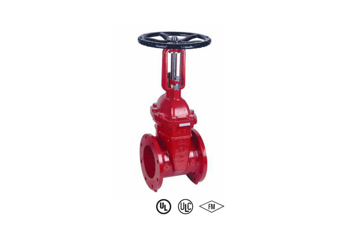
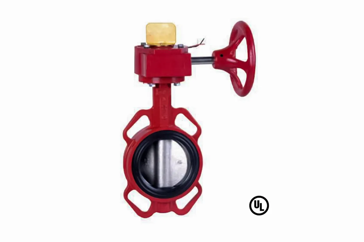
The Outside Screw & Yoke (OS&Y) Gate Valve is a critical component in fire protection systems, designed to meet NFPA standards for reliable performance. Constructed from durable materials like cast iron, ductile iron, or bronze, it is available in sizes ranging from 2″ to 12″, with custom options upon request. Featuring flanged or grooved end connections and a pressure rating of up to 300 PSI, this handwheel-operated valve ensures precise flow control. Its corrosion-resistant coating enhances longevity, while FM approval and UL listing guarantee compliance with industry safety standards. Ideal for fire sprinkler systems, commercial buildings, industrial facilities, and high-rise water supply systems, the OS&Y gate valve provides dependable shutoff and isolation in critical applications.
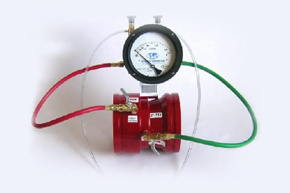
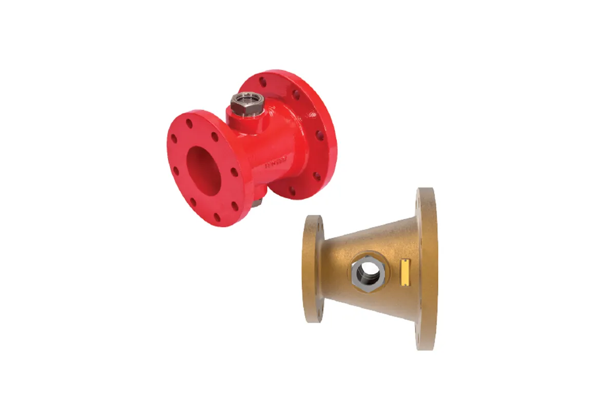
Our Venturi-type fire pump test meters deliver highly accurate and dependable flow measurement, ensuring your fire pumps meet performance requirements with confidence. By leveraging the Venturi effect, these meters provide precise flow data while minimizing pressure loss, maintaining system efficiency without disruption. Built from robust, high-quality materials, they are designed for long-term durability and reliability in demanding environments.
An essential tool for routine maintenance, performance verification, and compliance testing, these meters help uphold NFPA and other fire safety standards in commercial buildings, industrial plants, and municipal water systems. Trust our Venturi test meters to keep your fire protection systems operating at peak performance.
Line Size |
Pump GPM |
Meter Range Min. & Max. GPM |
Meter Range Min. & Max. LPM |
Model Number Grooved |
Model Number Butt Weld |
Model Number 150# Flanged |
Model Number <Threaded> *300# FLANGED* |
|---|---|---|---|---|---|---|---|
**1-1/4”
|
25
|
12.5 – 50
|
47 - 189
|
*1.25”-25-G
|
1.25”-25-B
|
* 1.25”-25-F
|
1.25”-25-T
|
**2”
|
50
|
25 – 100
|
95 - 379
|
* 2”-50-G
|
2”-50-B
|
* 2”-50-F
|
2”-50-T
|
**2-1/2”
|
100
|
50 - 200
|
189 - 757
|
2.5”-100-G
|
2.5”-100-B
|
2.5”-100-F
|
*2.5”-100-F3
|
3”
|
150
|
75 – 300
|
284 - 1136
|
3”-150-G
|
3”-150-B
|
3”-150-F
|
*3”-150-F3
|
3”
|
200
|
100 – 400
|
379 - 1514
|
3”-200-G
|
3”-200-B
|
3”-200-F
|
*3”-150-F3
|
* 4”-12” are also available.
* DENOTES NON-STOCK ITEM, PLEASE CHECK WITH FACTORY FOR AVAILABILITY
**SIZES 1-1/4”, 2”, 2-1/2″, & 14” ARE NOT FM APPROVED PER FACTORY MUTUAL**
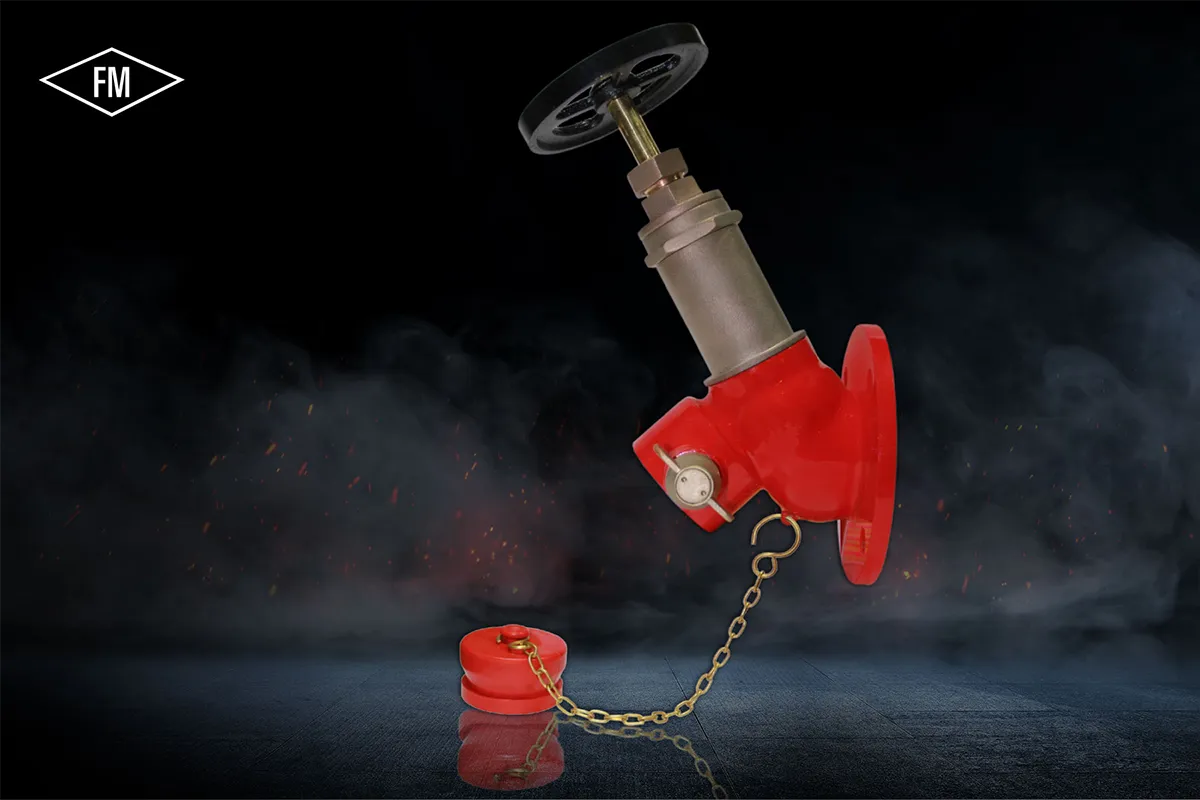
Pressure Reducing Valve has been designed to meet the needs of modern fire protection technology. It enables a uniform firefighting pressure to be maintained at any hydrant in a fire protection system irrespective of its location. Efficient pressure control is not affected by differences in inlet pressure that may occur at varying flow levels.
Expensive relief piping systems are completely eliminated, thus dramatically reducing installation costs. The regulator can be quickly and easily adjusted in-site to meet individual floor level pressure requirements.
Model Number |
NWR 123 |
NWR 124 |
|---|---|---|
Valve Type
|
Bib Nose, Threaded inlet
|
Bib Nose, Flanged inlet
|
Inlet Type
|
2½" Male BSP
|
3" ANSI class 150 FF
|
Outlet Type
|
1½" NH Male
| |
Pressure Rating
|
7 kg/cm2
| |
Nominal Size
|
DN 2½"
| |
Working Pressure
|
232 psi
| |
Test Pressure
|
64 kg/cm2 (Body test)
| |
Water Flow Rate
|
At inlet pressure is 10-12 bar the flow rate will be 250gpm (946lpm) @7bar outlet pressure.
| |
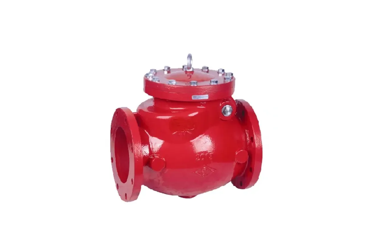
The Check Valve is a robust and dependable solution for controlling fluid flow in pipelines. Its durable construction ensures long-lasting performance, making it ideal for various industrial and municipal applications. The valve’s design allows smooth one-way flow while effectively preventing backflow, protecting systems from potential damage. Built to withstand demanding conditions, it offers excellent resistance to wear and corrosion. Easy to install and maintain, this swing check valve is a trusted choice for water supply, fire protection, and other critical systems where reliable flow control is essential. Its efficiency and durability make it a preferred option for engineers and contractors.
MODEL: SD-NRV300FF-D
in accordance with ANSI/AWWA C550
or diagonal square or fl at head
ANSI/AWWA C550
Model: SDBV-WTEC-300
Part |
Standard Specification |
|---|---|
Valve Body
|
ASTM A536, 65-45-12
|
Seat
|
EPDM & Backing
|
Disc
|
ASTM A536, 65-45-12
|
Stem
|
AISI 420
|
O-Ring
|
NBR
|
6 Bushing
|
PTFE
|
Signal Gear Box
|
ASTM A536, 65-45-12
|
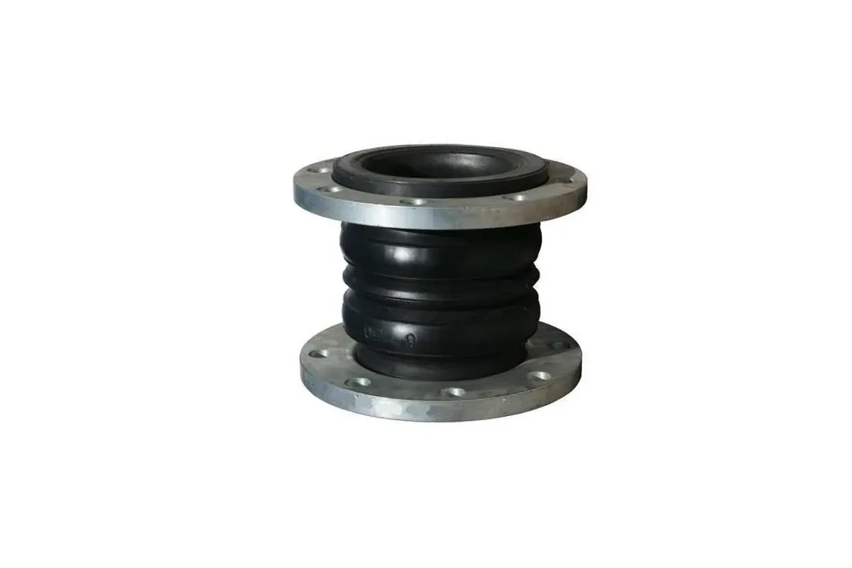
An expansion joint, also called a bellows, is a flexible connector designed to absorb movement, vibration, and thermal expansion in piping systems while maintaining a pressure-tight seal. Constructed from durable materials like stainless steel or rubber, it acts like a sealed spring to accommodate shifts without leaks or stress on the pipeline.
Material Specification:
Main Body: Polarized Rubber
Lining: Nylon Color Fabric
Frame: Hard Steel Wire
Flange: Mild Steel
Technical Specification
Working pressure: 15 Bar
Bursting Pressure: 45 Bar
Applicable Temp: 1150C
The WEST CONE Fire Safety Device offers a simple yet effective way to visually verify water flow in fire sprinkler systems, ensuring reliable operation when it matters most. Combining innovative design with user-friendly functionality, this essential tool provides instant confirmation that your fire protection system is working as intended. More than just a flow indicator, the WEST CONE represents a proactive approach to fire safety—helping protect properties, assets, and lives through immediate visual assurance of proper system performance. Its straightforward design makes it an indispensable component for maintaining compliant and effective fire protection in any environment.
Pressure Relief Valves
Optional Materials for Seawater and Severe Service Applications:
CK3MCuN (SMO 254)
(CE3MN)

Pressure Relief Valve is designed specifically to automatically relieve excess pressure in fire protection pumping systems. Pilot controlled, it maintains constant system pressure at the pump discharge within very close limits as demands change. The 50B-4KG1 and 2050B-4KG1 can be supplied with optional internal and external epoxy coating of the main valve wetted surfaces. On ductile iron valves, epoxy coating is standard.
MODEL: 2050B-4KG1
BRAND: CLA-VAL
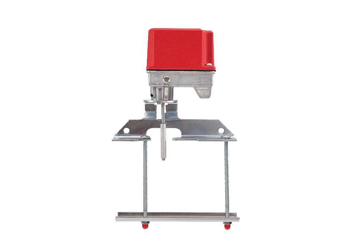
The SD-SVS OSY Series is used to monitor the open position of an OS&Y (outside screw and yoke) type gate valve. This device is available in three models; the SDSVS OSY-2, containing one set of SPDT contacts, the SD-SVS OSY-2, containing two sets of SPDT contacts and the SD-SVS OSY-2, containing two sets of SPDT and cover tamper. These switches mount conveniently to most OS&Y valves ranging in size from 2” to 12” (50mm to 300mm). They will mount on some valves as small as ½” (12.5mm).
Supervisory Switch shall be installed on each valve as designated on the drawings and/or as specified herein. Switches shall be mounted so as not to interfere with the normal operation of the valve and shall be adjusted to operate within two revolutions of the valve control or when the stem has moved no more than one-fifth of the distance from its normal position. The mechanism shall be contained in a die cast metal housing that provides a side entrance for ½” conduit and incorporates the necessary facilities for attachment to the valve. A grounding provision is provided. The switch assembly shall include two switches each with a rated capacity of 10 Amp @125/250VAC and 2.5 Amp @ 24 VDC. The supervisory switch shall be Underwriters Laboratories listed for indoor or outdoor use.
Weight |
0.6 Kg |
|---|---|
Enclosure
|
Cover : Die Cast Base : Die Cast Finish : Red Powder Coated All parts have corrosion resistant fnishes. |
Cover Tamper
|
Tamper Resistant Screws
Cover Tamper Switch Available
3 Amps 5 Amps at 125/250VAC
|
Contact Rating
|
SD-SVS OSY-1 : One Set of SPDT
SD-SVS OSY-2 : Two Sets ofSPDT
SD-SVS OSY-3 : Two Sets of SPDT
and Cover Tamper
10.0 Amps at 125/250 VAC
2.5 Amps at 30VDC Resistive
|
Conduit Entrance
|
One Knockouts and one hole for ½”
conduit provided
|
Temperature Range
|
32°F to 120°F ( 0°C to 49°C)
|
Service Use
|
• Automatic Sprinkler: NFPA 13 • One or Two Family Dwelling: NFPA 13D Residential • Occupancies up to 4 Stories: NFPA 13R National Fire Alarm • Code: NFPA 72 |
The Model SD-WFD is a vane type waterflow switch for use on wet sprinkler systems. The water flow contains two single pole, double throw, snap action switches and an adjustable, instantly recycling pneumatic retard. Vane-type waterflow detectors shall be installed on system piping as designated on the drawing and/or as specified herein.
Detectors shall have sensitivity in the range of 4 to 10 gallons per minute and a static pressure rating of 450 psi for 2˝–8˝ pipes. The flow condition must exist for a period of time necessary to overcome the selected retard period that is field adjustable. The delay mechanism shall be a sealed mechanical pneumatic unit with visual indication of actuation. The actuation mechanism shall include a polyethylene vane inserted through a hole in the pipe and connected by a mechanical linkage to the delay mechanism. Outputs shall consist of dual SPDT switches. Two conduit entrances for standard fittings of commonly used electrical conduit shall be provided on the detectors.
Brand- Shield
Flow Sensitivity Range |
4-10 GPM (15-38LPM) |
|---|---|
Contact Rating
|
Two sets of SPDT
8A@250VAC; 3A@24VDC;
2.5A@ 30VDC.
|
Working Pressure
|
450PSI.
|
Working Temperature
|
0°C to 68°C
|
Corrosion Protection
|
Fusion Bonded Epoxy Coated
Interior and Exterior or Enamel
Spray Paint, Interior and Exterior
|
Maximum Surge
|
18 FPS (5.5 m/s)
|
Corrosion Protection
|
Fusion Bonded Epoxy Coated
Interior and Exterior or Enamel
Spray Paint, Interior and Exterior.
|
Compatible Pipe
|
Steel water pipe, schedule 10
through 40
|
Conduit Entrances
|
Two openings for ½” conduit.
|
Service Use
|
• Automatic Sprinkler: NFPA 13 • One or Two Family Dwelling: NFPA 13D Residential • Occupancies up to 4 Stories: NFPA 13R National Fire Alarm • Code: NFPA 72 |

The SHIELD alarm check valve features a grooved seat alarm port, an external by-pass, and removable hand hole cover which hinged to a clapper assembly, it has both flanged inlet and outlet, the valve may be installed vertically on a wet pipe sprinkler system, which is used to lock water pressure fluctuations into the sprinkler system during providing the capability of initiating the required [re alarm through a water motor alarm or an electric pressure switch, which may use at constant pressure or variable pressure water supplies.
Wet Alarm Valves are designed to hold back water pressure in the piping system until the sprinkler is activated, to be used in wet pipe sprinkler installations in buildings not subject to freezing temperatures. Alarm Valve includes trim packages valves, gauges, pressure switch, fittings and nipples to provide retard chamber connection, drain connections and alarm test bybass.
MODEL: SD-ECO-AVA
TECHNICAL DATA :
Nominal Size _x0010_ |
150 & _x0010_00 NB |
|---|---|
End Connection
|
Flange x Flange
|
Rated Working Pressure _x0010__x0016_
|
175 PSI
|
Range o7 Working Pressure _x0010_
|
21 PSI TO 200 PSI
|
Testing Pressure _x0012_
|
350 PSI
|
Mounting
|
Vertical
|
Material
|
Grey Cast Iron
|
Flange Connection
|
ANSI B16.5 #150 ANSI B16.1 #125_x0010_ |
Flange Facing
|
Flat Face
|
Frictional Loss in Terms o7 Equivalent Length o7 Pipe C-120_x0007_
|
50 NB - 40ft _x0010_
100 NB - 40ft
|
Max. Flow Rate
|
150 NB - _x0016_790 gpm _x0010_
100 NB - 550 gpm
|
Non Actuating Flow Rate
|
Below 4 gpm
|
Weight _x0010_
|
190 NB - 37 Kg 100 NB - 20 Kg |
Ordering Information
|
SpeciBy Size oB valve, Flange Connection, Trim Details and Pipe OD
|
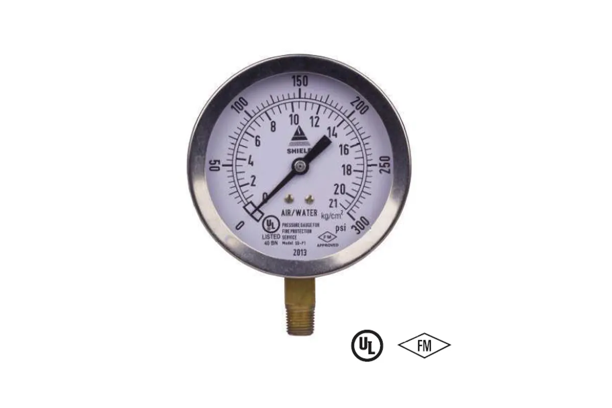
SD-P1 Pressure Gauge are specifically designed for Fire Sprinkler Services. The pressure gauge is UL Listed and FM approved. It has corrosion resistant polished stainless steel case and Bezel and Brass wetted parts. The dial has pressure reading in KG/ SQCM and PSI. The gauge window is hardened glass.
The pressure gauge must be mounted by square provided for spanner grip on the socket and not by turning the case. Turning of case will damage the gauge. Use PTFE tape around male threads of the gauge for sealing. Pressure gauge must be mounted in vertical position and isolated with valve or cock. The pressure gauge must be handled with due care for best results, the gauge should be stored in the original packing in which it has been shipped. It is advisable to ship the gauge in the same package for future transit.
The pressure gauge, which is visibly damaged, should not be installed. It is recommended that the pressure gauges must be inspected regularly for possible corrosion or damage. The gauge must be periodically calibrated as per requirement or as per local authority having jurisdiction.

The construction of the NAFFCO Air Release Valve has been designed with stainless steel trim to give years of smooth operation. The Air Release Valve should be mounted at the high points in a piping system to automatically remove pockets of air as they accumulate.
The valve can also be used to slowly release air in pump casings. This valve continuously eliminates air from a system by releasing small quantities of air before huge air pockets can happen.
When continuous accumulations of air in the pipeline occurs (lacking air release valves) this causes the flow capacity to slowly decrease hence power consumption also slowly increases which is unnoticeable at first, until flow drops dramatically, which can even lead to complete stop of the flow due to large quantity of air.
Another problem resulting from excessive air accumulation is un-explained pipeline rupture. These ruptures are passed off as the result of ground settling or defective pipe, where as in reality its large air pockets greatly increase pressure surges (normally occurring) when flow stops and starts causing the rupture.
VALVE OPERATION
The NAFFCO Air Release Valve, as got, is a typically open valve and will gradually vent air through the orifice. As liquid enters the valve, the float will rise, consequently shutting the opening. As air aggregates in the piping system and enters the valve, the float drops enabling the air to be vented out through the opening.
The lever component gives mechanical advantage to the orifice. Amid system operation, the pipeline pressure applies a solid upward drive on the sealing com- ponent, the orifice button.
The lever instrument amplifies the heaviness of the float with the goal that the hole will open under high pipeline pressures. Extra ports are accommodated flushing, testing and draining purposes. This cycle automatically repeats as air accumulates inside the air release valve, thereby preventing the formation of air pockets.
Sizes: |
½”, ¾”, 1” |
|---|---|
Pressure Rating:
|
175 psi
|
Body and Cover
|
Ductile Iron ASTM A536 65-45-12
|
Float
|
Stainless Steel 316, ASTM A240
|
Internal Parts
|
Stainless Steel 316, ASTM A240
|
Orifice Button
|
EPDM
|
Paint Specification
|
Red Epoxy Painted
|
Operational Highlights
|
• Maintains system flow efficiency • Releases unwanted air pockets during system operation • Protects system against air related surges |

A ball valve is a simple yet efficient quarter-turn valve that controls flow using a hollow, rotating ball. When the ball’s opening aligns with the pipe, fluid or gas flows freely. A quick 90-degree turn shuts off the flow completely by blocking the passage. The attached handle provides clear visual confirmation—parallel to the pipe means open, while perpendicular means closed. This straightforward design ensures reliable operation, making ball valves a popular choice for quick shut-off applications in plumbing, industrial systems, and gas lines. Their durability and ease of use make them ideal for both manual and automated flow control.
– 42 Bar for ¼” to 2”
– 28 bar for 2½” to 4”
MODEL: SD-BLVT95
Description |
Material |
|---|---|
Valve Body
|
Brass
|
Bonnet
|
Brass
|
Seal Teflon
|
PTFE
|
Ball
|
Chrome
Plated Brass
|
Stem
|
Brass
|
Seal Ring
|
Tefon - PTFE
|
Stem Packing
| |
Gland Screw
|
Brass
|
Handle
|
Steel
|
Nut
|
Steel
|

Pressure Reducing Valve has been designed to meet the needs of modern fire protection technology. It enables a uniform firefighting pressure to be maintained at any hydrant in a fire protection system irrespective of its location. Efficient pressure control is not affected by differences in inlet pressure that may occur at varying flow levels.
Expensive relief piping systems are completely eliminated, thus dramatically reducing installation costs. The regulator can be quickly and easily adjusted in-site to meet individual floor level pressure requirements.
Model Number |
NWR 123 |
NWR 124 |
|---|---|---|
Valve Type
|
Bib Nose, Threaded inlet
|
Bib Nose, Flanged inlet
|
Inlet Type
|
2½" Male BSP
|
3" ANSI class 150 FF
|
Outlet Type
|
1½" NH Male
| |
Pressure Rating |
7 kg/cm2 | |
|---|---|---|
Nominal Size
|
DN 2½"
| |
Working Pressure
|
232 psi
| |
Test Pressure
|
64 kg/cm2 (Body test)
| |
Water Flow Rate
|
At inlet pressure is 10-12 bar the flow rate will be 250gpm (946lpm) @7bar outlet pressure.
| |

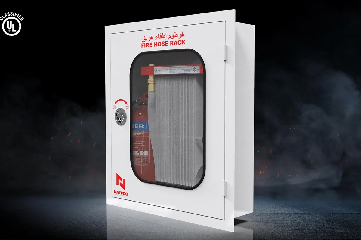
NAFFCO Fire hose racks are designed for use in controlling incipient fire by building occupant use and conform to NFPA 14 standards for CLASS II service. The Fire Hose Racks are manufactured to comply UL & FM standard.
1.Angle Valve or pressure reducing type valve (UL/FM approved).
2.Hose Rack frame material made of stainless
-Brush Finish
-Mirror Finish
-RED (RAL 3000) Powder Coated Oven Baked
3.Hose rack nipple.
4.Hose coupling.
5.Fire Hose – 30 (UL Listed/FM Approved).
Available Hose Color: Red/White
6.Fog nozzle. (UL approved).
Model Number
|
NHR 38V
|
NHR 64V
|
UL/FM approved
|
FM approved
|
FIRE HOSE
| ||
Fire Hose Type
|
Single jacket, Light weight Thermoplastic lining with high tenacity filament polyester yarn, UL listed
|
Single jacket, Light weight Thermoplastic lining with high tenacity filament polyester yarn, UL listed
|
Size & Color
|
1½" x 30 m., White
|
2½" x 30 m., White
|
Service Pressure
|
250 psi
|
250 psi
|
Proof Pressure
|
500 psi
|
500 psi
|
Burst Pressure
|
750 psi
|
750 psi
|
COUPLINGS
| ||
Type
|
1½" NH Female Thread- ed Coupling, Brass
|
2-½" NH Female Thread- ed Coupling, Brass
|
ANGLE VALVE
| ||
Working Pressure
|
300 psi
|
300 psi
|
Test Pressure
|
600 psi
|
600 psi
|
NOZZLE
| ||
Inlet Size
|
1.5" Female NST Threaded
|
2.5" Female NST Threaded
|
Discharge rate
|
130±5 GPM @ 100 psi
|
280 GPM @ 100 psi
|
(in full spray pattern)
| ||
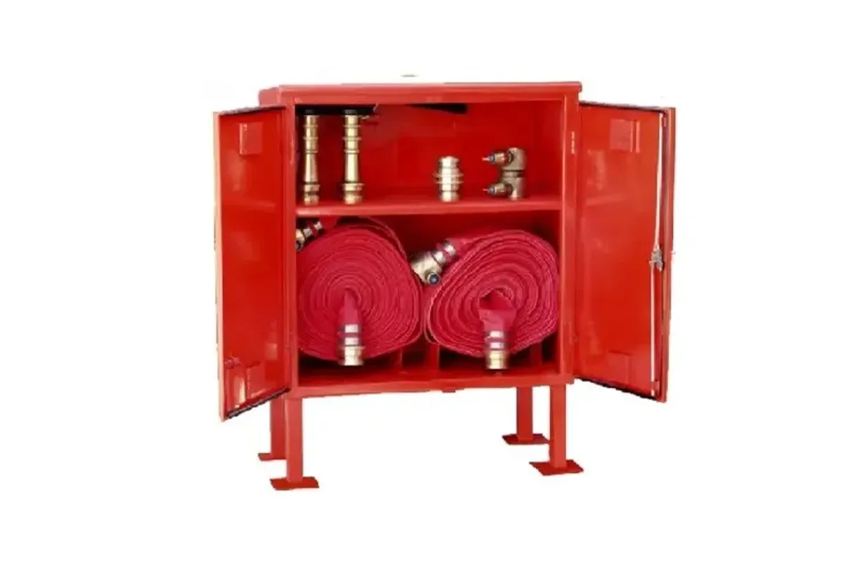
Fire hose cabinets provide a secure and organized storage solution for fire fighting equipment like hoses and water connections. Built with high-quality steel or stainless steel, these durable cabinets resist wear and maintain a clean, professional appearance. They come in different styles to fit various spaces, including surface-mounted or recessed options for a seamless look. Whether for horizontal or vertical installation, Fire hose cabinets offer flexibility to meet different building needs. Trusted globally in prestigious properties, these cabinets ensure fire safety equipment is easily accessible while blending with modern interiors. Custom designs are also available for specialized requirements.
CABINET MODEL |
CABINET SIZE |
CABINET TYPE |
CABINET MATERIAL |
CABINET FINISH |
HOSE RACK MODEL |
HOSE RACK SELECTION | |||
|---|---|---|---|---|---|---|---|---|---|
NHRC 38-A/ES
|
750x700x200
|
Surface Mounted
|
Min. 1.2mm EG Steel Sheet
|
Epoxy Powder Coated
|
NHR 38V
|
HR 38XA
|
SS 304 - RAL 3000
|
1.5" Angle Hose Valve Double Female NPT (SD-AV)
| |
HR 38YA
|
SS 304 - Brush Finish
| ||||||||
HR 38ZA
|
SS 304 - Mirror Finish
| ||||||||
800x700x200
|
Surface Mounted
|
Min. 1.2mm EG Steel Sheet
|
Epoxy Powder Coated
|
NHR 38V
|
HR 38XB HR 38YB |
SS 304 - RAL 3000 SS 304 - Brush Finish |
1.5" Angle Hose Valve Female NPT Inlet x Male NH (SD-AV)
| ||
HR 38YB
|
SS 304 - Brush Finish
| ||||||||
HR 38ZB
|
SS 304 - Mirror Finish
| ||||||||
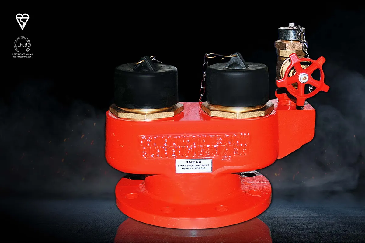
Breaching inlets are suitable for installation on dry risers, in a building for fire fighting purposes, fitted with inlet connection at fire brigade access level and outlet connection at specified points, which is normally dry but capable of being charged with water by pumping from fire service appliances.
The breaching inlets are manufactured to comply with BS 5041 PART-3:1975 standard comprising of male instantaneous connections complying with BS 336:2010, drain valves complying with BS 5154, PN16 rated and non-return valves.
The breaching inlets and its fittings are suitable for a normal working pressure of 10 bar.
Model Number |
NDR 095 |
|---|---|
Inlet Connection
|
2 Nos. Male Instantaneous Connector Complying to BS 336
|
Pressure Rating
|
Normal Working Pressure of 10 bar
|
Nominal Size
|
100 mm Flanged Outlet
|
Test Pressure
|
BS 4504 Part: 2:1974 Table: 16/21
|

Breeching inlets are suitable for installation on dry risers, in a building for fire fighting purposes, fitted with inlet connection at fire brigade access level and outlet connection at specified points, which is normally dry but capable of being charged with water by pumping from fire service appliances.
The breeching inlets are manufactured to comply with BS 5041 PART-3:1975 standard comprising of male instantaneous connections complying with BS 336:2010, drain valves complying with BS 5154, PN16 rated and non return valves.
The breeching inlets and its fittings are suitable for a normal working pressure of 10 bar.
BSI Kitemark and LPCB certified.
Body material made of spheroidal graphite cast iron (Ductile Iron) to BS 1563:2011.
Inlet connection and non-return valve material made of copper alloy to BS 12163:2011.
Each inlet connections are fitted with a non-return valve and are of spring loaded mushroom type.
Each breeching inlet is painted RED internally and externally.
Breeching inlet Model NWRX115 for Dry Risers with elevated working pressure of 16 bar and the performance verified by BSI.
Model Number |
NWR 115 & NWRX 115 |
|---|---|
Inlet Connection
|
4 Nos. Male Instantaneous Connector Complying to BS 336
|
Pressure Rating
|
Normal Working Pressure of 10 bar
|
Nominal Size
|
150 mm Flanged Outlet
|
Test Pressure
|
20 bar
|
Flange Drilling
|
BS 4504 Part: 2: 1974 Table: 16/21
|
Temperature Range
|
0° - 38°C
|

Name |
Material |
|---|---|
Hydrant Body
|
Ductile Iron, ATM A536 65-45-12
|
Chain Ring
|
Steel, Zinc Plated
|
Pumper Nozzle Cap
|
Cast Iron, ASTM A126 Class B
|
Pump Nozzle
|
Bronze, ASTM B62 C83600
|
Pumper Nozzle Gasket
|
Rubber, NBR
|
41/2" Main Valve
|
Rubber, NBR
|
41/2" Main Valve Retainer
|
Bronze, ASTM B62 C83600
|
Screw M4x10
|
Stainless Steel, AISI304
|
41/2" Main Valve Holder
|
Stainless Steel, AISI304
|
Holder Nut
|
Bronze, ASTM B62 C83600
|
Screw M4x12
|
Stainless Steel, AISI304
|
Stem-1
|
Stainless Steel, AISI304
|
Hose Nozzle Cap
|
Cast Iron, ASTM A126 Class B
|
Hose Nozzle Gasket
|
Rubber, NBR
|
Hose Nozzle
|
Bronze, ASTM B62 C83600
|
21/2" Main Valve Retainer
|
Bronze, ASTM B62 C83600
|
21/2" Main Valve
|
Rubber, NBR
|
21/2" Main Valve Holder
|
Stainless Steel, AISI304
|
Stem-2
|
Stainless Steel, AISI304
|
21/2" Stem Nut
|
Bronze, ASTM B62 C83600
|
Operating Nut
|
Bronze, ASTM B62 C83600
|
Nut M12
|
Stainless Steel, AISI304
|
O-Ring 25x3.55
|
Rubber, NBR
|
Stem-3
|
Stainless Steel, AISI304
|
41/2" Stem Nut
|
Bronze, ASTM B62 C83600
|
O-Ring 49x2.65
|
Rubber, NBR
|
O-Ring 136x3.55
|
Rubber, NBR
|
O-Ring 85x3.55
|
Rubber, NBR
|

The single jacket fire hose consists of 100% polyester plain-woven synthetic and natural rubber linings. This fire hose has very good resistance to ageing and abrasion. The light fire hose is suitable for normal situation.
The single jacket hose made of high tenacity polyester staple and polyester filaments. Lining is natural rubber. Jacket is plain. There is a special adhesion between the jacket and the rubber.
Model No. |
Diameter |
Service Test Pressure (Bar/Psi) |
Hydrostatic Strength Test Presure (Bar/Psi) |
Standard Compliance/ Approvals |
|---|---|---|---|---|
NF-FH38
|
1.5
|
14/200
|
50/725
|
UL19,NFPA 1961/
UL listed
|
NF-FH65
|
2.5
|
14/200
|
50/725
|
*NH threaded. Storz & instantaneous coupling or other types are available upon request.
Self Standing Hose Cabinets are designed to accommodate fire hose reel, fire fighting equipment and breeching inlet. Fire hose reel cabinets are manufactured to comply with BSEN 671-1 standard and breeching inlet cabinets are manufactured to comply to BS 5041-5 standard.
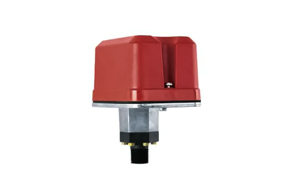
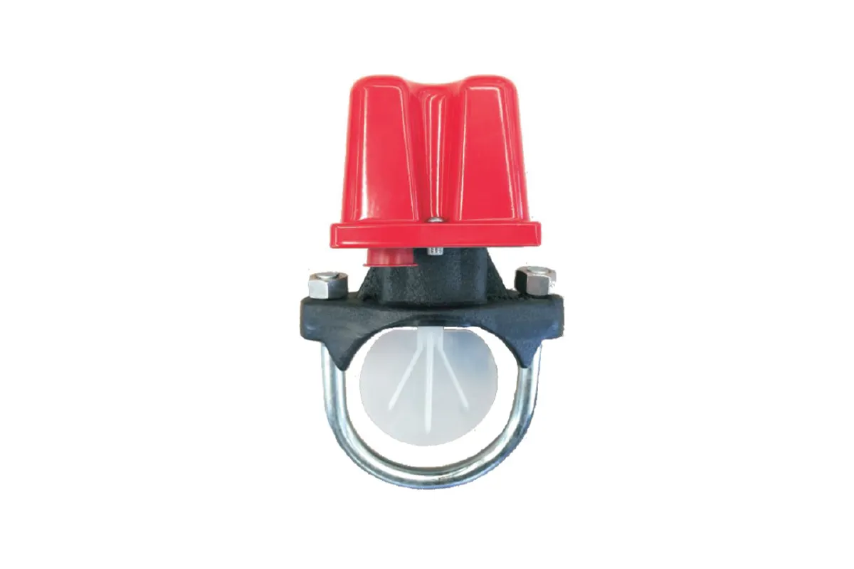
The SD-PS Series Pressure Switches shall be installed on the sprinkler system with connection as shown on the drawings and for as specified herein. Pressure switches
shall be of the bellows-activated type. Switches shall have a maximum service pressure rating of 300 psi and shall be factory adjusted to operate at a pressure of 4 – 8 psi. There shall be one (1) or two (2) SPDT contacts rated at 10.0 Amp @ 125/250 VAC and 2.5 Amp @ 30 VDC. The contractor shall furnish and install, where indicated on the plans, pressure switches according to appropriate NFPA standards.
Switches shall be provided with a ½˝ NPT male pressure connection to be connected to the alarm check valve of a “wet” sprinkler system, into the intermediate chamber of a “dry” system, or to a pre-action or deluge valve. They shall be activated by any flow of water equal to or in excess of the discharge from one sprinkler head. Switches shall provide 1 knockout type and 1 open hole for ½˝ conduit fitting attachment and a ground screw provision for electrical grounding. The switch enclosure shall be weatherproof. The cover shall incorporate tamper-resistant screws. The unit shall be listed by Underwriters Laboratories, Inc. and approved by Factory Mutual.
Maximum Adjustment Pressure Range
APPROXIMATE DIFFERENTIAL
At Safety Source Ltd, we are passionate about creating safer environments through innovative fire protection solutions.
House # 10 (Level-4), Road # 02 (Arab Ali Member Road), Ward # 53, Diabari, Turag, Dhaka-1230.
© 2025 Safety Source. All Rights Reserved. Developed by Khan IT