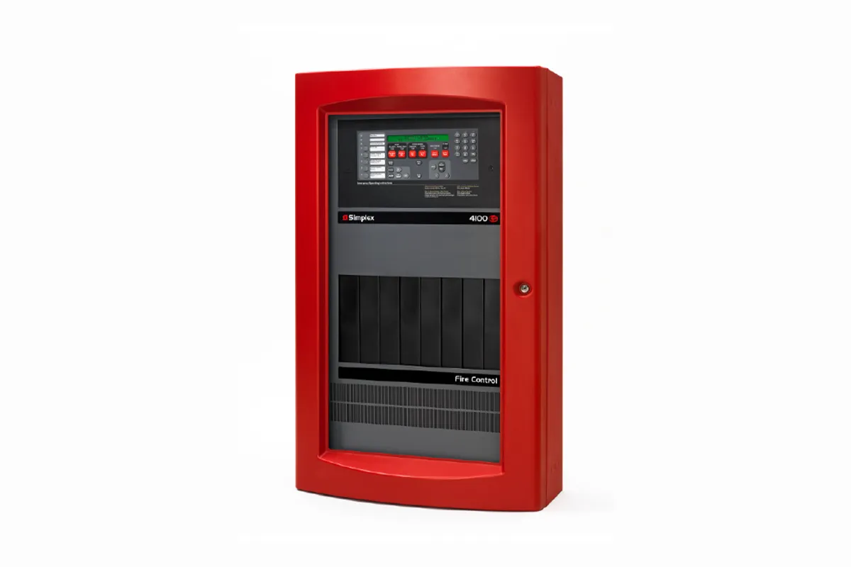
4100ES fire panels provide extensive installation, operator, and service features with point and module capacities suitable for a wide range of system applications. An on-board Ethernet port provides fast external system communications to expedite installation and service activity. Dedicated compact flash memory archiving provides secure on-site system information storage of electronic job configuration files to meet NFPA 72 (National Fire Alarm and Signaling Code) requirements.
Mechanical Description
Specification |
Rating | |
|---|---|---|
Maximum Distance ohms
from Control Panel per
Device Load
|
1 - 125
|
4000 ft (1219 m); 50
ohms
|
126 - 250
|
2500 feet (762 m); 35
ohms
| |
Total Wire Length Allowed With “T” Taps for
Class B Wiring
|
Up to 12,500 ft (3.8
km);
0.60 μF
| |
Maximum Capacitance Between IDNet 2
Channels
|
1 μF
| |
Loading per device
|
Loading per device 0.8 mA supv., 1 mA
alarm;
2 mA per activated
device LED
| |
Wire Type and Connections
|
Shielded or unshielded,
twisted or untwisted
wire*
| |
Connections
|
Terminals for 18 to 12
AWG (0.82 mm2 to 3.31
mm2)
| |
IDNet 2 and IDNet 2+2 Module Compatibility: IDNet communicating devices and TrueAlarm sensors including QuickConnect and QuickConnect2 sensors
| ||
Note: * Some applications may require shielded wiring. Review your system with your local Simplex product supplier.
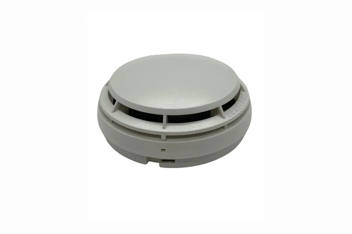
TrueAlarm analog sensors provide an analog measurement that is digitally communicated to the host control panel using Simplex addressable communications.
At the control panel, the data is analyzed and an average value is determined and stored. An alarm or other abnormal condition is determined by comparing the sensor’s present value against its average value and time.
TrueAlarm multi-sensor model 4098-9754 combines the established performances of a TrueAlarm photoelectric smoke sensor with a fast-acting and accurate TrueAlarm thermal sensor to provide both features in a single sensor/base assembly.
General Operating Specifications (refer to data sheet list for additional detail)
Communications and Sensor Supervisory Power |
4100ES, 4100U, or 4010ES IDNet communications, 1 address per base |
|---|---|
UL Listed Operating Temperature Range
|
32° F to 100° F (0° C to 38° C)
|
Operating Temperature Range |
15° F to 122° F (-9° C to 50° C |
|---|---|
Storage Temperature Range
|
0° F to 140° F (-18° C to 60° C)
|
Humidity Range
|
10 to 95% RH
|
Smoke Sensor Sensitivity Range
|
0.2 % to 3.7% per foot of smoke obscuration, selected at control panel (refer to
additional information on page 2)
|
Smoke Sensor Air Velocity Range
|
0-4000 ft/min (0-1220 m/min)
|
Thermal Sensor Operation (selected at control panel)
|
Fixed alarm temperature setting of 135° F (57.2° C), and/or rate-of-rise
temperature alarm at 15° F (8.3° C) or 20° F (11.1° C), also selectable as utility
monitoring operation from 32° F to 122° F (0° C to 50° C)
|
Housing Color
|
Frost White
|
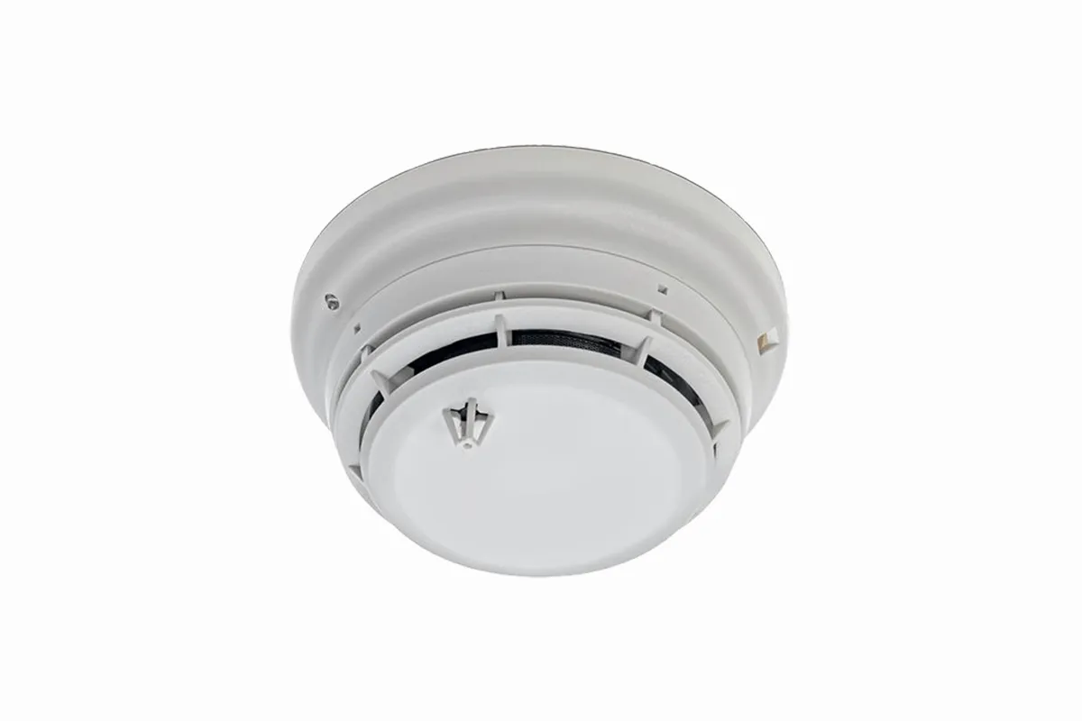
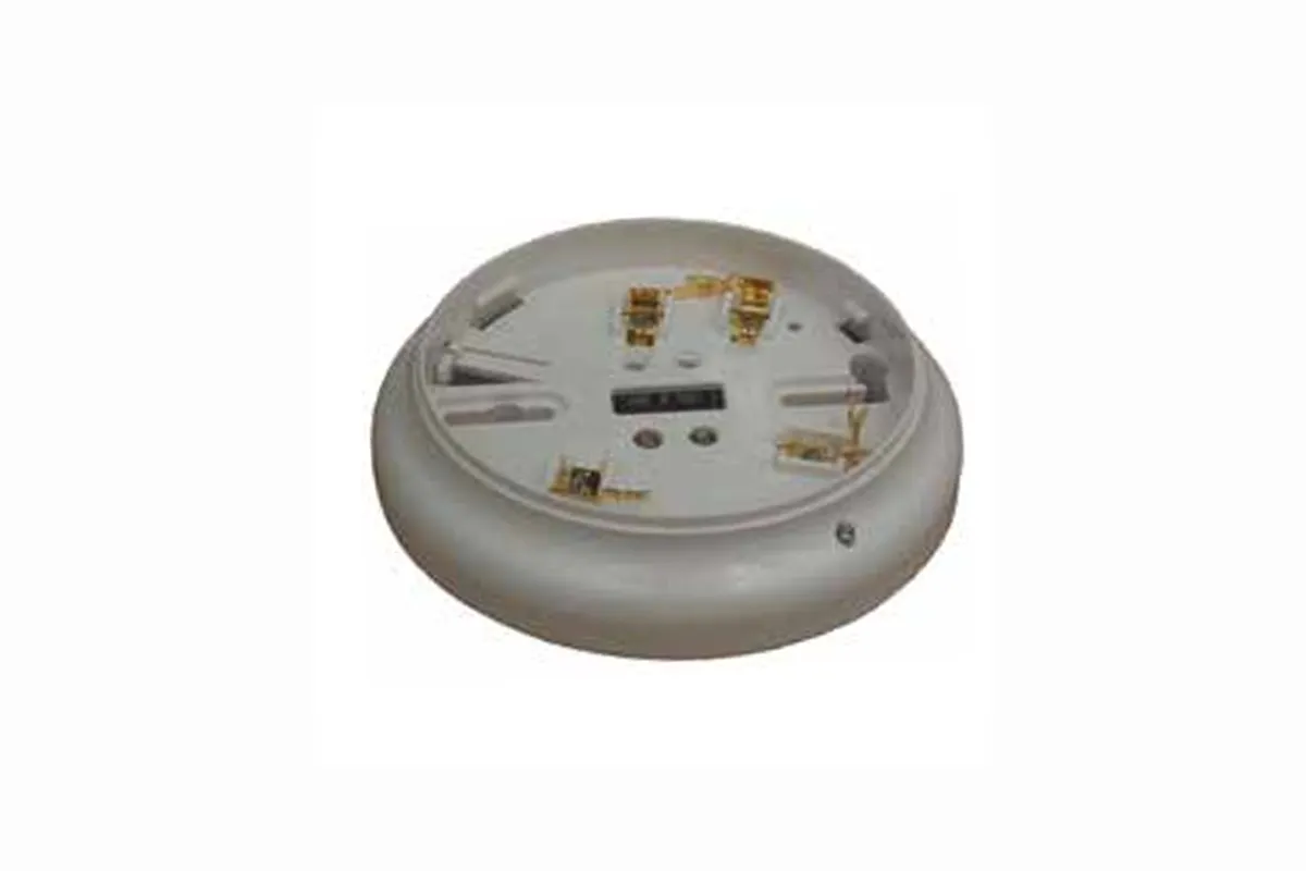
TrueAlarm sensor bases contain integral addressable electronics that constantly monitor the status of the detachable photoelectric, ionization, or heat sensors. Each sensor’s output is digitized and transmitted to the system fire alarm control panel every four seconds. Since TrueAlarm sensors use the same base, different sensor types can be easily interchanged to meet specific location requirements
This feature also allows intentional sensor substitution during building construction. When conditions are temporarily dusty, instead of covering the smoke sensors (causing them to be disabled), heat sensors may be installed without reprogramming the control panel. Although the control panel will indicate an incorrect sensor type, the heat sensor will operate at a default sensitivity providing heat detection for building protection at that location.
Communications and Sensor Supervisory Power |
MAPNET II or IDNet, auto-select, 24-40 VDC w/data, 400 μA typical, 1 address per base |
|---|---|
Communications Connections
|
Screw terminals for in/out wiring, 18 to 14 AWG (0.82 mm2 to 2.08 mm2)
|
Remote LED Alarm Indicator Current |
1 mA typical, no impact to alarm current | |
|---|---|---|
Remote LED Alarm Indicator and Relay Connections
|
Color coded wire leads, 18 AWG (0.82 mm2 )
| |
UL Listed Temperature Range
|
32° to 100° F (0° to 38° C)
| |
OperatingTemperature Range
|
with 4098-97 Operating 17 or 4098 -9733
|
32° to 122° F (0° to 50° C)
|
Operatingwith 4098-9714
|
Operating15° to 122° F (-9° to 50° C)
| |
OperatingHumidity Range
|
Operating
10 to 95% RH
| |
Smoke SensorAmbient Ratings
|
4098-9714, Photoelectric Sensor
|
Air velocity = 0-2000 ft/min (0-610 m/min)
|
4098-9717, Ionization Sensor
|
Air velocity = 0-400 ft/min (0-122 m/min); Altitude is up to 8000 ft (2.4 km)
| |
Housing Color
|
Frost White
| |
4098-9791 Base With Supervised Remote Relay 2098-9737 (see page 2 for contact ratings)
| ||
Externally Supplied Relay Coil Voltage
|
18-32 VDC (nominal 24 VDC)
| |
Supervisory Current
|
270 μA, from 24 VDC supply
| |
Alarm Current with 2098-9737 Relay
|
28 mA, from 24 VDC supply
| |
4098-9822 Unsupervised Relay, Requirements for Bases 4098-9789 and 4098-9791 (see page 2 for contact ratings)
| ||
Externally Supplied Relay Coil Voltage
|
18-32 VDC (nominal 24 VDC)
| |
Supervisory Current
|
Supplied from communications
| |
Alarm Current
|
13 mA from separate 24 VDC supply
| |
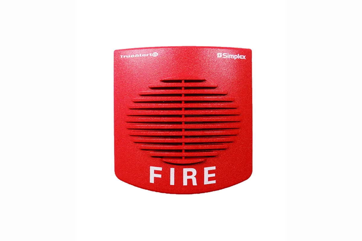
TrueAlert ES addressable horns are individually addressed audible notification appliances that receive power, supervision, and control signals from a Simplex fire alarm control panel providing IDNAC Signaling Line Circuits (SLCs).
Sound Characteristics |
2400 to 3700 Hz sweep, modulated at 120 Hz rate |
|---|---|
Temperature Range
|
32° to 122° F (0° to 50° C)
|
Humidity Range
|
10% to 93%, non-condensing @ 104° F (40° C)
|
Connections
|
Terminal blocks on mounting plate for 18 AWG to 12 AWG (0.82 mm2 to 3.31 mm2); two wires per
terminal for in/out wiring
|
Installation Instructions
|
579-1034
|
IDNAC SLC Wiring Specifications
(refer to control panel installation
instructions for more information)
|
Maximum wire length allowed with "T-Taps" for Class B wiring per SLC = 10,000 ft (3048 m)
|
Maximum wire length to any appliance = 4000 ft (1219 m)
|

TrueAlert ES addressable A/Vs are individually addressed audible/ visible notification appliances that receive power, supervision, and control signals from a Simplex FACU providing IDNAC Signaling Line Circuits (SLCs).
Sound Characteristics |
2400 Hz to 3700 Hz sweep, modulated at 120 Hz rate |
|---|---|
Temperature Range
|
32°F to 122°F (0°C to 50°C)
|
Humidity Range
|
10% to 93%, non-condensing @ 104°F (40°C)
|
Installation Instructions
|
579-1031
|
Connections
|
Terminal blocks on mounting plate for 18 AWG to 12 AWG (0.82 mm2 to 3.31 mm2); two wires per
terminal for in/out wiring
|

Convenient installation and alignment
Simplex addressable beam smoke detector includes the proven FireRay 5000 system features, of auto-aligning infrared beam smoke detection combined with IDNet addressable communications. If the detector head is installed using the easyfit mounting system, an integral laser can be activated that aligns along the optical path of the infrared beam. Positioning the reflective prism is quick and accurate using the Auto-Align beam alignment feature.
AutoOptimise Beam Alignment
The AutoOptimise beam alignment system automatically directs and maintains the beam in the optimum position for reliable performance. The transmitter element generates the signal, the prism reflects it back to the receiver element, and then it is analyzed for the presence of smoke. The beam control station flags an alarm condition if it reaches the predetermined level. Alarm threshold levels are set using the host FACU. Time to Fire and Time to Fault are set using the beam control station.
Mounting reference
The maximum distance of the detector and the reflector from the ceiling must be 10% of the distance between the floor and ceiling. Lateral detection may be up to 30 ft (9.144 m) on either side of the beam, providing a maximum total coverage area of up to 19,800 square feet, 60 ft x 330 ft (18.29 m x 100 m). Refer to the installation instructions supplied with the product and to NFPA 72 (National Fire and Signaling Code) for additional installation guidance.
Communications to the host control panel
To investigate the beam heads remotely, the host FACU receives status and numerical information from the beam controller. The beam controller receives commands and the Smoke and Almost Dirty threshold levels are set using the host FACU.
Numerical information received
Numerical information received includes Signal Strength in percent, to compare to alarm threshold level set by host FACU and Compensation Level, an indication of beam status and dirt accumulation.
Application note
Reflective beam smoke detectors may not be suitable for areas with highly reflective surfaces. Separate transmitter or receiver models may be required. Refer to NFPA 72 and contact your Simplex product representative for additional applications guidance.
Mechanical and general reference
Specification |
Rating |
|---|---|
Housing
|
Flame Retardant ABS, IP rating = IP54
|
Finish
|
Light grey/black
|
Simplex Addressable interface and host control panel programming instructions.
|
579-1039, additional operating and installation instructions ship with the product.
|
Electrical
Input voltage |
14 VDC to 36 VDC, supplied from agency listed fire alarm power supply. | ||
|---|---|---|---|
Input current
|
50 mA
| ||
Power wiring to controller
|
Terminal block connections; 18 AWG to 14 AWG (0.82 mm2 to 2.08 mm2)
| ||
Wiring, controller to head
|
328 ft (100 m) maximum distance, use twisted wire pair; 18 AWG to 16 AWG (1 mm2 to 1.5 mm2 )
| ||
Beam optical wavelength
|
850 nm
| ||
Communications reference
|
Details
|
IDNet addressable communications, communications circuit is isolated from input power, and controller-to-head communications.
| |
Compatibility reference (review for addition to installed systems)
|
IDNet Communications source
|
Firmware/revision
| |
4100ES and 4010ES Control Panels
|
System Firmware 2.02 or higher
| ||
Operating Specifications
Sensitivity threshold |
Selectable from 10% to 60%; with 35% as default (this is % of beam obscuration drop from 100%). The value is selected using the host FACU and communicated by IDNet communications. |
|---|---|
Operating distance range
|
26 ¼ ft. to 330 ft (8 m to 100 m)
|
Beam status indicators
|
Multi-color LED on bottom front of beam detector head: Normal = Green; Alarm = Red; Fault (Trouble) = Yellow; LED flash is every 10 seconds.
|
Service status indicators
|
One LED for each detector, located under the beam controller cover, indicates the status of the beam detector channel communications.
|
Trouble conditions
|
Communications fault, Rapid Obscuration fault (blocked beam), Excessively Dirty, and Summary trouble (other general troubles not detailed).
|
UL listed temperature Range
|
32°F to 100°F (0°C to 38°C)
|
Operating temperature range
|
-4°F to 131°F (-20°C to 55°C), for indoor use only.
|
Operating humidity range
|
0% to 93% RH, non-condensing.
|
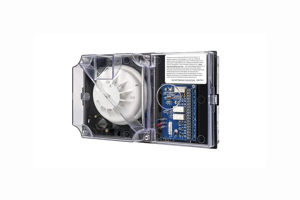
Simplex duct detectors can quickly sense when smoke is traveling through ducts and enable HVAC airflow to be shut down or redirected to contain smoke dispersion.
IDNet Relay IAMs allow fire alarm control panels to control a remotely located Form “C” contact using IDNet addressable communications for both data and module power. Typical applications would be for switching local power for control functions such as elevator capture, or control of HVAC components, pressurization fans, dampers, etc. Relay status is also communicated requiring only one device address.
Individual Addressable Relay Module (Relay IAM):
Communications |
IDNet Communcations, 1 address per device |
|---|---|
Relay IAM Power
|
Supplied by IDNet communications
|
Contact Ratings (not rated for incandescent switching)
| |
Type
|
Form C SPDT
|
Power limited
|
2A @24 VDC, resistive
| ||||
1 A @ 24 VDC, inductive
|
1 A @ 24 VDC, inductive From listed fire alarm supply
| ||||
Nonpower limited
|
0.5 A @ 120 VAC resistive
| ||||
Wire Connections
|
Screw terminals for in/out wiring 18 to 14 wire (.82 to 2.08)
| ||||
IDNet
Communications Wiring Reference
|
Up to 2500 ft (762m) from control panel
| ||||
Up to 10000 ft (3048m) total wiring distance (including T-Taps)
| |||||
Compatible with Simplex 2081-9044 over voltage protector
| |||||
Dimensions
|
41/8" H x 41/8" W x 13/5" D (105 mm x 105 mm x 35 mm)
| ||||
Housing Material
|
Black thermoplastic
| ||||
Mounting Plate
|
Sheet metal, galvanized
| ||||
Temperature Range
|
32° to 120° F (0° to 49° C), intended for indoor operation
| ||||
Humidity Range
|
Up to 93% RH at 100° F (38° C)
| ||||
Installation Instructions
|
574-184
| ||||
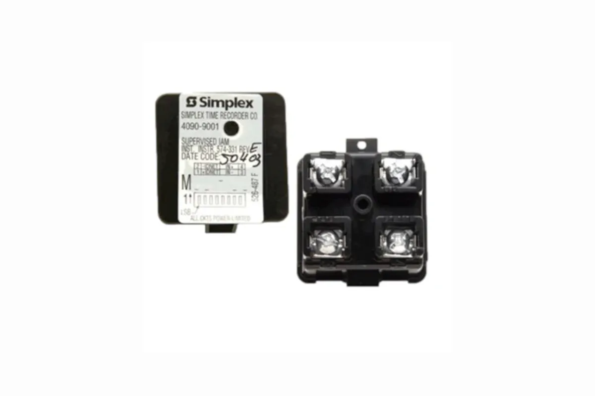
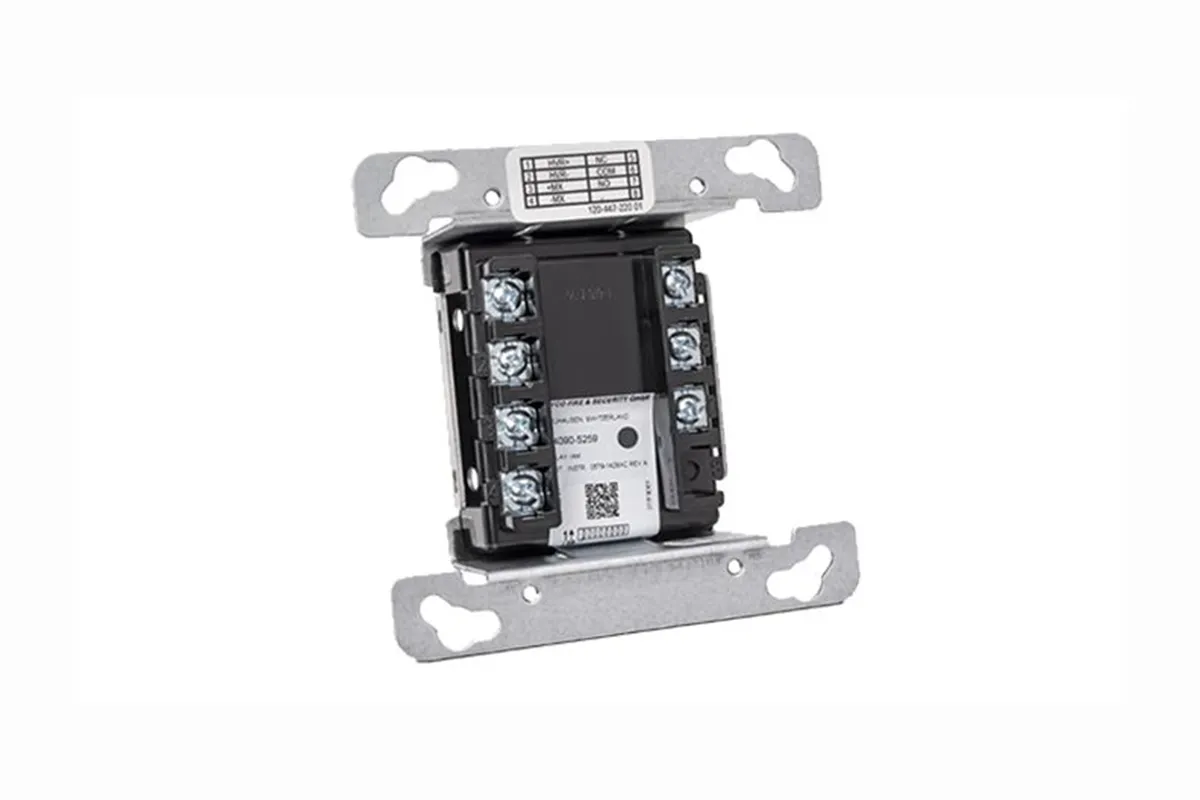
Individual addressable modules (IAMs) receive both power and communications from a two-wire MAPNET II or IDNet circuit. They provide location specific addressability to a single initiating device (such as single station smoke detector alarm contacts or heat detector contacts) or multiple devices at the same location by monitoring normally open dry contacts and the wiring to an end-of-line resistor. Model 4090-9001 is packaged in a thermoplastic housing and provides screw terminal connections and a status indicating LED.
Electrical | ||
|---|---|---|
Power and Communications
|
MAPNET II or IDNet, auto selected, 1 address per IAM
| |
Input Requirements
|
Normally open, dry contacts
| |
Wire Connections
|
4090-9001
|
Screw terminals for in/out wiring, 18 to 14 AWG wire
(0.82 mm2 to 2.08 mm2)
| |
4090-9051
|
Color coded wire leads, 18 AWG (0.82 mm2), 8” long (203 mm)
| ||
Reference Documents
|
Installation Instructions
|
574-331 for 4090-9001; 579-572 for 4090-9151
| |
Field Wiring Diagrams
|
842-073 for IDNet operation; 841-804 for MAPNET II operation
| ||
Wiring Distances
| |||
Distance from IAM to Contacts
|
500 ft (152 m) maximum without protectors
| ||
400 ft (122 m) maximum with 2081-9044 Overvoltage Protectors
| |||
Wiring Distance Reference per channel, MAPNET II or 2500 ft (762 m) maximum from fire alarm control panel
IDNet Communications
|
2500 ft (762 m) maximum from fire alarm control panel
| ||
10,000 ft (3048 m) maximum total wiring distance (including T-Taps)
| |||
Mechanical
| |||
Dimensions
|
4090-9001
|
1-9/16” W x 1-3/4” H x 1-1/4” D (40 mm x 44 mm x 32 mm)
| |
4090-9051
|
1-9/16” W x 1-9/16” H x 9/16” D (40 mm x 40 mm x 14 mm)
| ||
Housing Material, 4090-9001
|
Black thermoplastic
| ||
Encapsulation Material, 4090-9051
|
Epoxy, beige
| ||
Temperature Range
|
32° to 120° F (0° to 49° C) intended for indoor operation
| ||
Humidity Range
|
Up to 93% RH at 100° F (38° C)
| ||
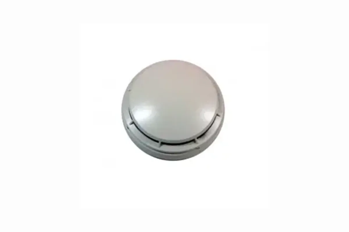
The TrueAlarm detector base contains integral addressable electronics that constantly monitors the status of the detachable detector. Detector types can be easily interchanged to meet specific location requirements, for example during building construction or maintenance. The device address is contained in the base, so the address remains with its programmed location when the detector is removed for service. An integral red LED indicates power-on by pulsing, or alarm or fault when steady on.
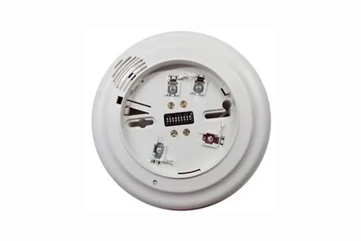
The Simplex 4098-9794 is a modular TrueAlarm sensor base with built-in electronic alarm sounder. The Piezoelectric sounder provides high output (88 dBA) with low current requirements (20 mA) and is interchangeable with TrueAlarm sensors; photoelectric, heat or ionization (ordered separately). The 4098-9794 sounder bases are for use with Simplex® control panels model 4010, 4020, 4100, 4100U, 4120, and Universal Transponders.
General Operating Specifications | ||
|---|---|---|
Communications and Sensor Supervisory Power
|
MAPNET II or IDNet, auto-select, 24-40 VDC w/data, 400 A typical, 1 address per base, supplied by control panel
| |
Communications and Sounder Power Connections
|
Screw terminals for in/out wiring, 18 to 14 AWG
| |
Remote LED Alarm Indicator
|
Current
|
1 mA typical supplied from communications, no impact to alarm current
| |||
LED Connections
|
Color coded wire leads, 18 AWG
| ||||
UL Listed Temperature Range
|
32° F to 100° F (0° C to 38° C)
| ||||
Operating Temperature Range
|
With 4098-9717 or 4098-9733
|
32° F to 122° F (0° C to 50° C)
| |||
With 4098-9714
|
15° F to 122° F (-9° C to 50° C)
| ||||
Humidity Range
|
10 to 95% RH
| ||||
Smoke Sensor Ambient Ratings
|
4098-9714, Photoelectric Sensor
|
Air velocity is 0-2000 ft/min (0-610 m/min)
| |||
4098-9717, Ionization Sensor
|
Air velocity is 0-400 ft/min (0-122 m/min); Altitude is up to 8000 ft (2.4 km r
| ||||
Housing Color
|
Frost White
| ||||
At Safety Source Ltd, we are passionate about creating safer environments through innovative fire protection solutions.
House # 10 (Level-4), Road # 02 (Arab Ali Member Road), Ward # 53, Diabari, Turag, Dhaka-1230.
© 2025 Safety Source. All Rights Reserved. Developed by Khan IT